
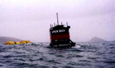
SPERBOYTM Pilot Unit in Action
SPERBOYTM, developed and patented by Embley Energy, is a floating wave energy converter based on the 'oscillating water column' principle. Air displaced by the oscillating water column is passed through turbine-generators. Designed to be deployed in large arrays 8 to 12 miles off shore SPERBOYTM provides large-scale energy generation at a competitive cost.
With a minimum number of moving parts, which are above the surface of the sea, maintenance requirements are minimised and energy is produced at a very competitive rate. Current research is looking to extend the life of the vessel to some 50 years and includes several initiatives to deliver higher levels of power. Consequently the device has considerable potential for further reducing the cost of delivered power.
The absence of large quantities of invasive products such as oils and lubricants coupled with minimal impact on seabed ecosystems makes the device environmentally friendly.
SPERBOYTM has completed the Marine Energy Challenge, where independent
consultants investigated its performance in terms of power capture as well as
carrying out a detailed study of both capital and maintenance costings to arrive
at their prediction for the cost of delivered power. The device is now ready
to exploit the very successful and encouraging results of this 'Challenge' and
will now proceed to the deployment of full-scale prototypes.
 |
 |
|
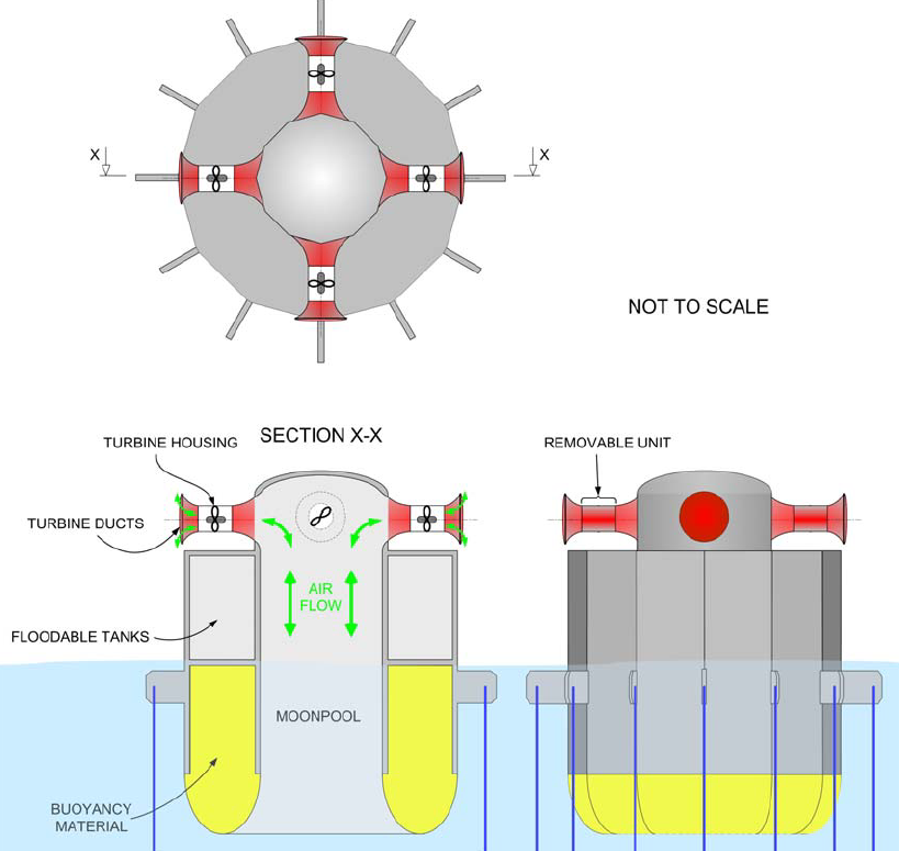
Evolution of multi-column to single column, General
layout of SPERBOYTM
|
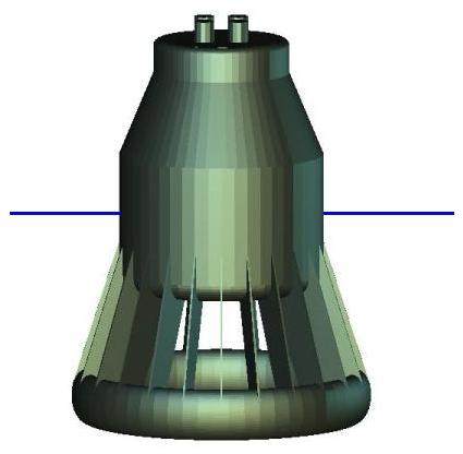
Latest SPERBOYTM concept 2007
|
| DESCRIPTION OF OPERATING PRINCIPLE |
SPERBOYTMis a floating
buoy Oscillating Water Column (OWC) device consisting of a buoyant structure
with a submerged & enclosed column. Housed above the OWC on top
of the buoy is all the plant, turbines, generators and associated system
facilities. The principle of operation is similar to that of fixed OWC’s
designed for shoreline and fixed installations. |
| HISTORY OUTLINE |
1994 – 1998 Multi- tube OWC wave energy device concept devised, small scale models tested and patents secured. 1997-8 Funding secured from The European Commission in the frame work of the Non Nuclear Energy Programme JOULE III for research funding. 1999 – 2001. Research conducted at the U. of Plymouth culminating in a 1/5th size pilot device deployed south of Plymouth Sound. 2001 – 2003. Extensive computer modelling studies. 2003. Computer modelling prompted a change from multi to single tube concept. 2003 – 2005. SPERBOYTM participated in the U.K. Carbon Trust’s Marine Energy Challenge. Independent consultants investigating its performance in terms of power capture as well as carrying out detailed study of both capital, operating and maintenance costing in arriving at their prediction for the cost of delivered electrical energy. 2005/6. Further support secured from The Carbon Trust and nPower to conduct a two year study, in association with Trafalgar Marine, entitled 'Advanced Concrete Structural Design of the SPERBOYTM Wave Energy Converter’. Sub-contractors include W. S. Atkins & Co. and H.M.R.C., Cork. 2006. Agreement with Great Western Research to sponsor a Ph.D. programme at the Universities of Bath & Plymouth to further develop “Storm survivability and tuning strategies applicable to the SPERBOYTM Wave Energy Converter”. 2007. Project work with the Universities of Bristol and The West of England |
| STRUCTURAL MATERIALS |
Floating buoy constructed
using composite concrete materials |
| DIMENSIONS |
Dimensions vary depending
on sea conditions at deployment site. Max envisaged – Diameter:
30M. Overall Height: 50M, Draft: 35M. Circular in plan – invariant
to wave direction. |
| PREFERENTIAL DEPLOYMENT DEPTH |
Greater than 50M, but less
if located in less active seas using smaller device. |
| MOORING CHARACTERISATION |
The mooring system composes
of three or four diametric tethers to subsurface floats moored to suitable
seabed fixings. |
| SEA BOTTOM CONDITIONS REQUIREMENTS |
All conditions acceptable
given suitable seabed fixings are attainable. |
| INSTALLED POWER PER UNIT |
The annual energy production
is clearly dependent on the wave climate at the deployment site. However,
the study carried out during the Carbon Trust’s Marine Energy Challenge
concluded, conservatively, that 450 kW mean annual output per device
would be obtained at Benbecula, in the Outer Hebrides (or Western Isles)
off the coast of Scotland. |
| IDENTIFICATION OF TECHNOLOGICAL RISKS | Technological risks are: Storm survivability, potential mooring and air turbine failure are all being assessed, researched and eliminated by design. For example all air turbines are well clear of water ingress and no moving parts below the waterline. Computer modelling and tank testing assess energy capability. |
(A cross indicates the present stage of development)
| CONCEPTUAL DESIGN |
Researched and tested in
the 1999 – 2001 research program |
|
| TANK
TESTING |
Tank testing was included
in the 1991 to 2001 research programme to correlate data mathematically
generated and that collected from the pilot deployment. It included
regular and irregular trialsThe current programme supported by the Carbon
Trust (2005/06) includes 2 tank testing programs. This will also cover
both regular and irregular wave spectrum |
|
| SCALE TESTING – SEA TRIALS |
1/5th scale tested in the
1999 – 2001 research program. Results published by University of
Plymouth |
|
| X | PRE-ENGINEERING |
Substantially competed under
Carbon Trusts ‘Marine Energy Challenge’ |
| X | DETAILED ENGINEERING |
Vessel design work current
with the support of The Carbon Trust. |
| FULL-SCALE PROTOTYPE – DESIGN, CONSTRUCTION, TESTING |
Since the device is designed for specific sites this will not commence until a funding package has been assembled. Current work provides the framework and foundation for this to commence immediately. |
| DEPLOYMENT PROCEDURE |
1) Install anchors |
| INFRASTRUCTURES
REQUIRED FOR DEPLOYMENT |
Deployment requires very
little in terms of permanent infrastructure. The main body of the device
can be manufactured in a location close to the site, floated out, transported
and deployed by suitable vessels. All the skills required are similar
to most offshore sectors and can be introduced as required. The actual
deployment location will determine infrastructure required. |
| FARM GEOMETRY |
All current work has focused on the deployment of a 10-device farm. However this is not the optimum for commercial and operational considerations. Spacing is around 350 meters, depending on water depth, with a full size farm of 1000 devices requiring up to 10 – 15 square kilometres.mouth |
| MAINTENANCE STRATEGY |
Routine maintenance would
be carried out on the device with major works requiring the units of
modular design being replaced and taken back to shore for refurbishment.
The design aim is a zero maintenance requirement. |
| REQUIRED EQUIPMENT FOR MAINTENANCE |
Appropriate support vessel
is required with the necessary capability. Current vessels have the
capacity to be utilised and no new configurations are envisaged. |
| REMOVAL TO LAND PROCEDURE |
This is a simple reversal of the deployment procedure. |
Click here to email us for further information: INFORMATION